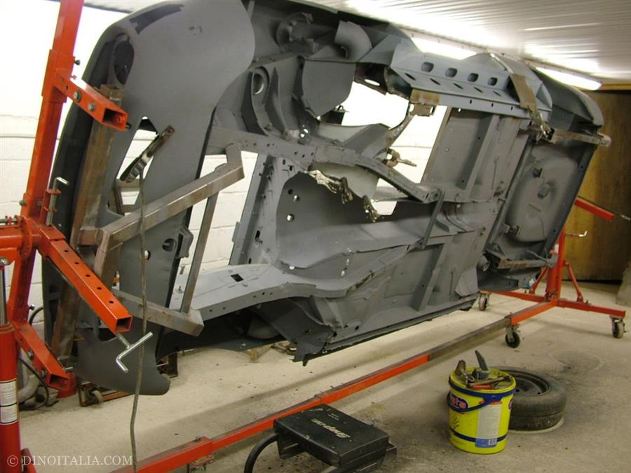
Fiat Dino Spider 2400 Restoration
We started with the driver's side of the car. The most important thing is to put strength back into the structure of the shell, so it's best to replace the sills/rocker panels first. A new sill set was constructed with all the factory holes and flanges replicated. Next, we de-constructed the sills carefully so as not to distort or damage any of what we want to keep. The inner sill needed some repairs. It is best to leave this panel in place if possible as it will keep everything in check as the floors, outriggers and A and B-posts attach to it. Obviously on a car where this is beyond repair, steps will need to be taken to brace the structure before removing the sill section.With the inner sill repaired, we were then able to fit the boxing plate and top and bottom closing panels. Braces were then fitted to carry the stress of the A and B-pillars. We re-made these as the originals were damaged and poorly repaired. The top closing panel has a finishing piece fitted to box it in. This forms the sill step plate inside the door jamb. A new step plate was fabricated and then fitted.
Next, repairs were made to the A-post. A new A-post triangulation plate was made and fitted. This helps to strengthen and brace the stress of the door hinge carriers. If these are not in good condition the door can drop when opened, making it difficult to shut. Also, scuttle shake will be increased on a car where these parts are in poor condition.
The inner sill boxing plate needs to be fixed behind the B-post, so the rear quarter panel was removed to gain access. The quarter panel was in poor condition around the edges where it meets the sills and the rear wheel arch so a new one was made and then fitted. The return on the rear wheel tub also required replacement as it was corroded. This was then spot welded to the quarter panel as per factory. An inner seal closing panel was fabricated and then fitted to finish the sill end.
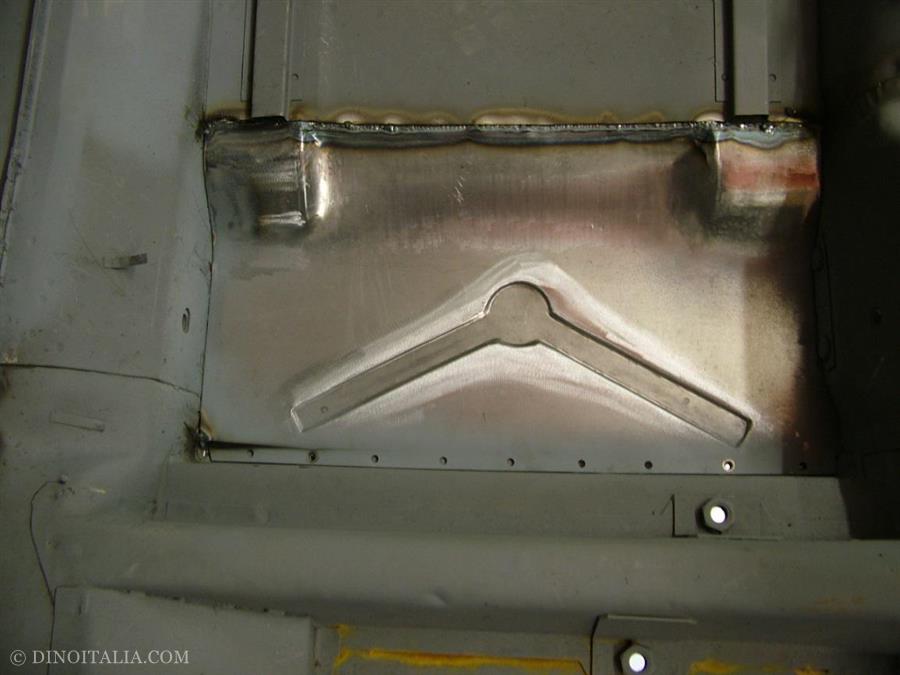
With strength back in the sills, attention could then turn to the floors. The forward half of the front floor pan was removed. The rear could be saved. Ahead of the front floor pan is the lower edge of the bulk head. This was also removed, along with the lower half of the front wheel tub. The outrigger and jacking point were in good order, needing only a little straightening. A bit of heat from the oxy torch was used to ease the outrigger back into shape. A new lower bulkhead was made and fitted, followed by a new lower wheel tub, with all pressings and returns replicated as per factory. Next, a front floor section was made with a tension to replicate the centre stiffening rib with the drain hole. The floor was then welded in. You can see from the photos that a seamless fit was achieved. A new rear floor pan was then made and fitted in place of the original rusty one.
Front Chassis Repairs
The front chassis rail had suffered badly with corrosion and botched repairs. A plate had been welded over the steering box mount. This was removed to reveal historic cracking of the mount area. The re-enforcing sections that stop the chassis rail crushing as the steering box is tightened to it, were actually exposed. The steering box must have worked loose at some stage causing it to flex on its securing bolts, causing this damage. Great care was taken to de-construct the chassis rail and then repair. Inside the chassis rail there are re-enforcing plates that carry the captive nuts for the engine/suspension cross member and the anti-roll bar U-clamps. These were re-made and then fitted, then checked against the factory chassis alignment settings. The inside of the chassis rail was cleaned up, treated with rust inhibitor and zinc primed before being enclosed with a new lower chassis rail section.
Rear Suspension Mounts
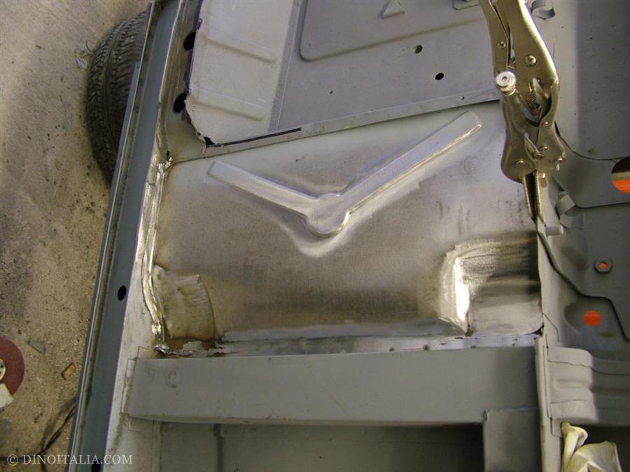
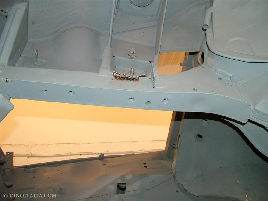
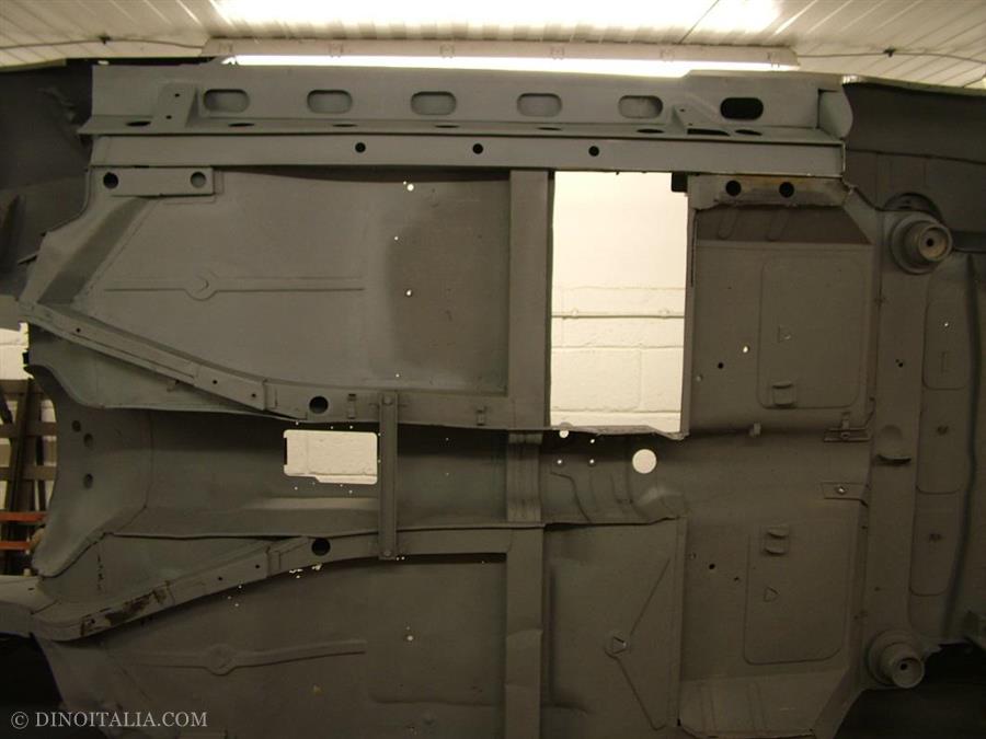
The independent rear suspension (IRS) unit pivots from a front mount. This is bolted up through the floor, directly below the rear seat squab. This area has to carry all the stresses and strains of the rear suspension and rear axle. All of the torque loading from the rear wheels is transmitted into this area under acceleration or braking. Fitting the IRS was originally an after-thought by Fiat (the unit was borrowed from the 130 range, although they are not interchangeable as the geometry is slightly different. Also, the rear brakes are unique in a Dino). The area where the front mount locates is not really strong enough to take all these stresses and tends to crack so it was not surprising to find small cracks in this area. These were welded up and re-enforcing plates were made and then fitted so as to eliminate this issue in future.
Here we have our starting point - the exposed original sills. The outer sill has been removed prior to blasting to enable the inner structure to be cleaned.

Newly constructed sill set. The outer sill will be made at a later date when we do the front lower wings.
Repairs to inner sills.
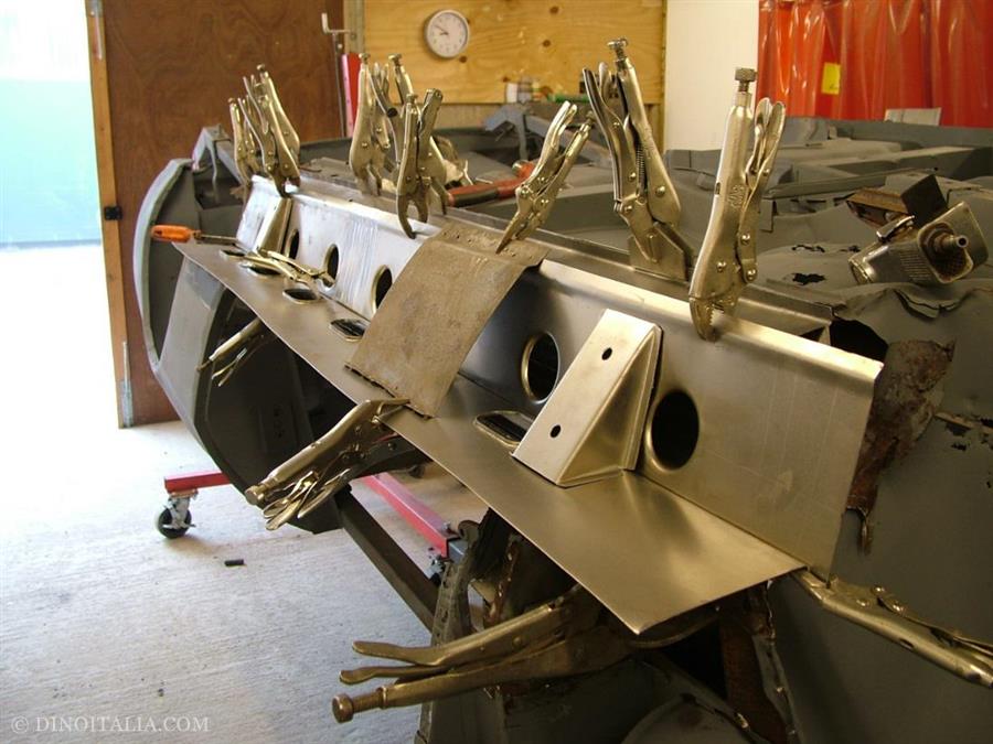
Trial fitting the sill sections. We are using a small piece of an original Dino sill to aid alignment.
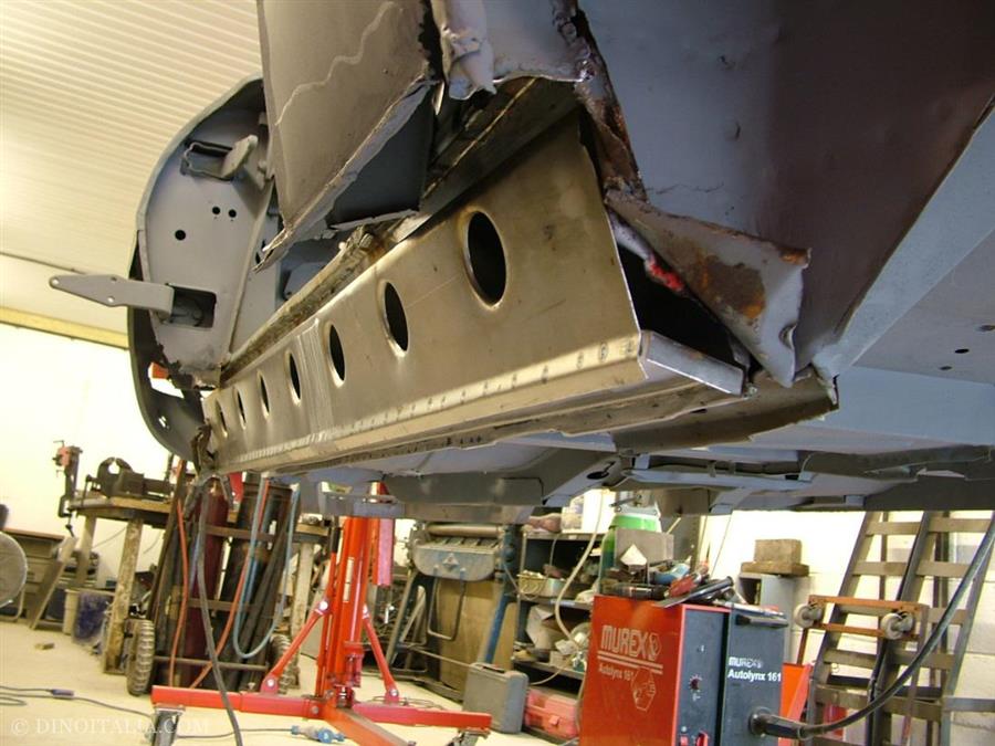
Boxing plate and lower closing panel fitted.
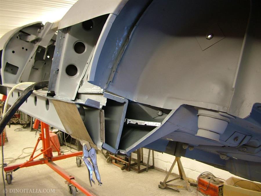
Top closing plate being checked for alignment.
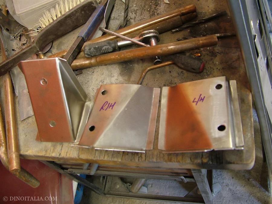
New A and B-post strengthening panels fabricated.
Inner sill boxing plate attaches behind the rear quarter panel.
A-post triangulation panel removed. Also, sill step has been removed.
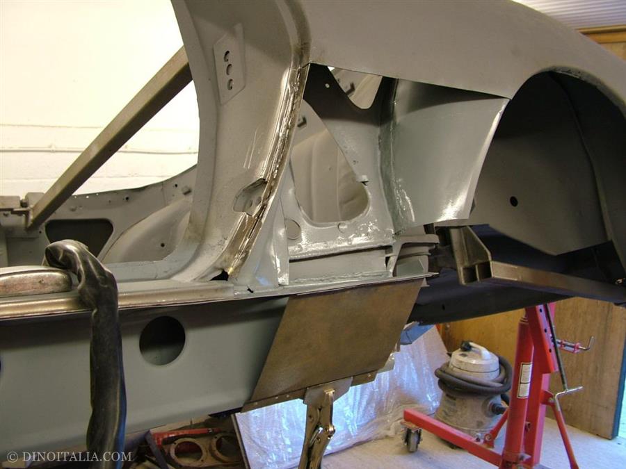
A-post triangulation panel replaced.
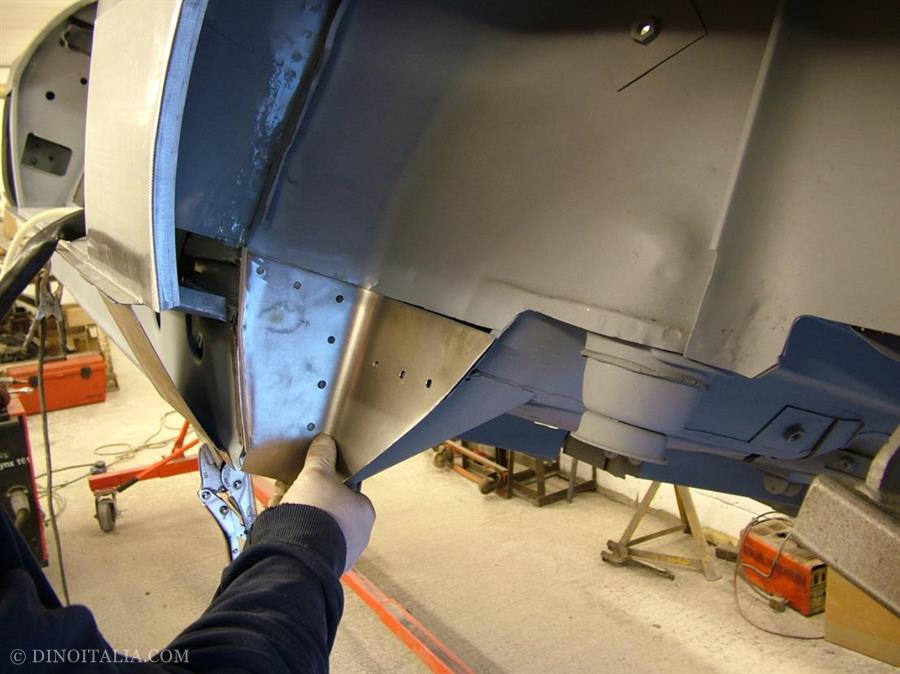
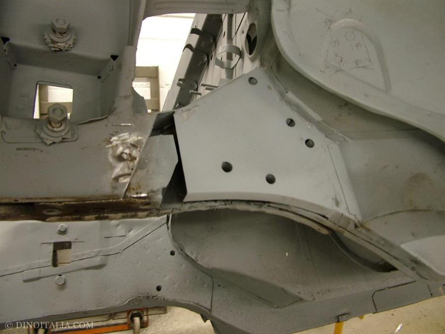
New lower wheel tub, fabricated and then fitted.
Rear sill closing panel.
New inner sills.
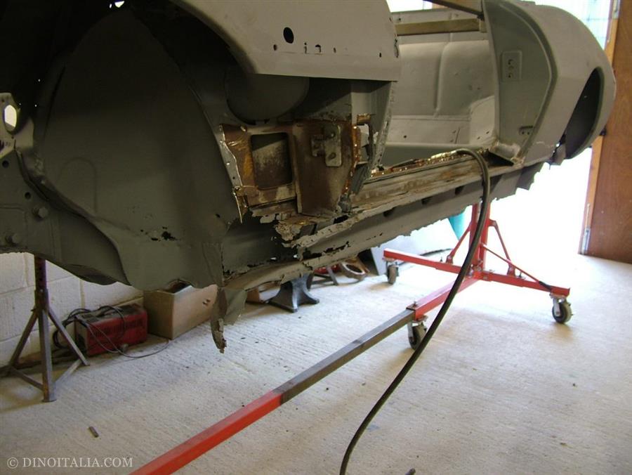
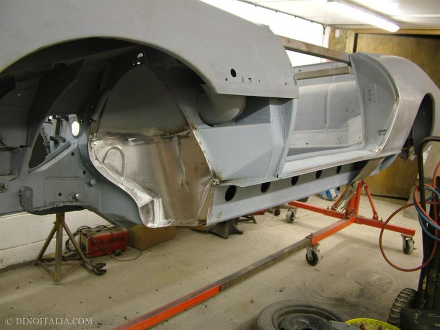
New sills fitted. Front floor, lower bulkhead and wheel tub removed.
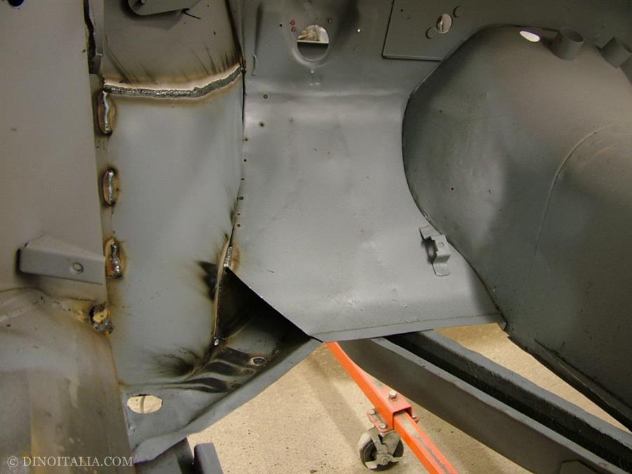
New lower bulkhead and wheel tub fitted. Note the accelerator pedal stop bracket.
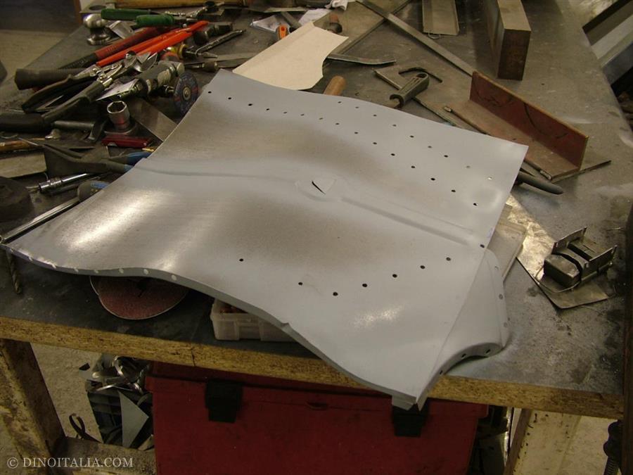
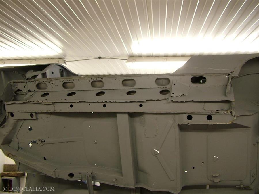
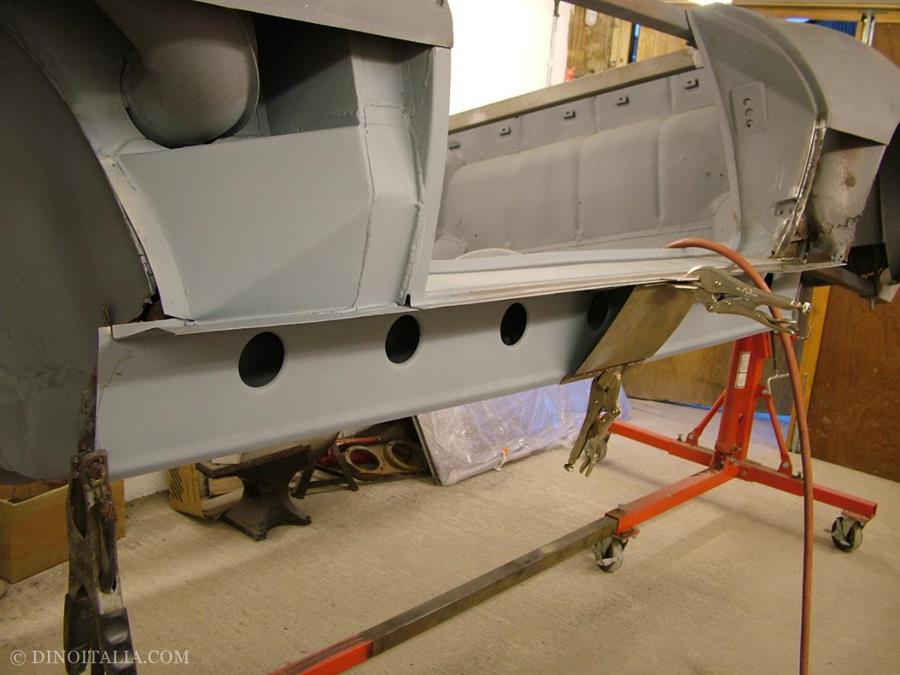
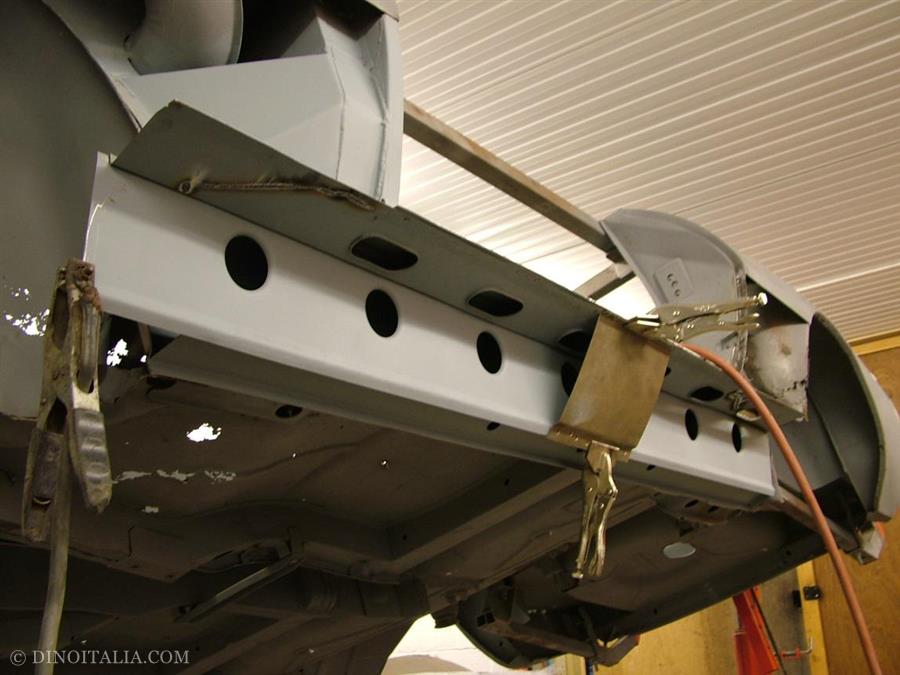
New front floor pan fabricated. The holes will enable us to mig plug it to the chassis rails.
New rear floor pan under construction.
Rear floor pan fitted. The drain hole is yet to be made.
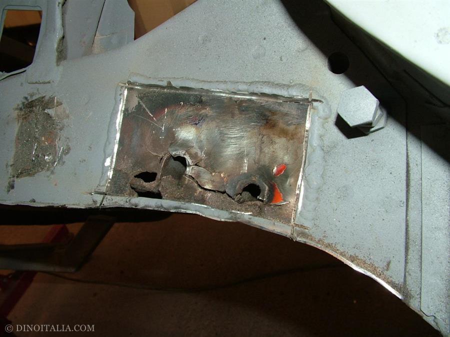
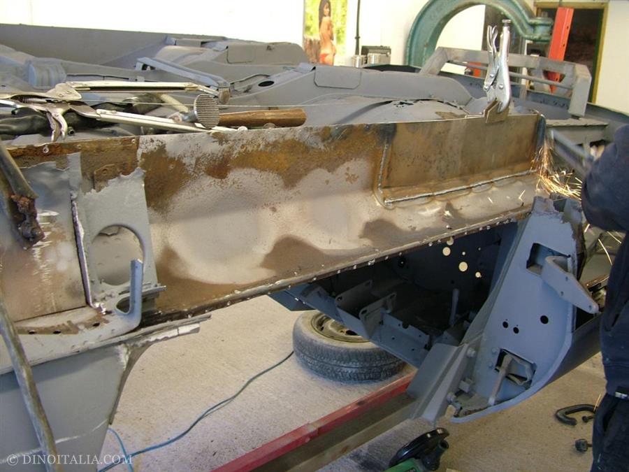
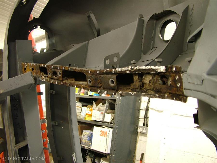
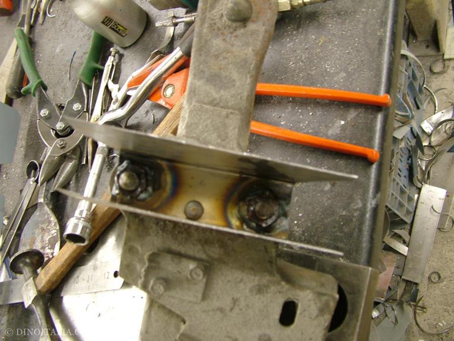
Front steering box mount area of front chassis rail. We have removed the plate that was covering up the damage. You can clearly see the stiffener panels poking through the cracked and damaged area.
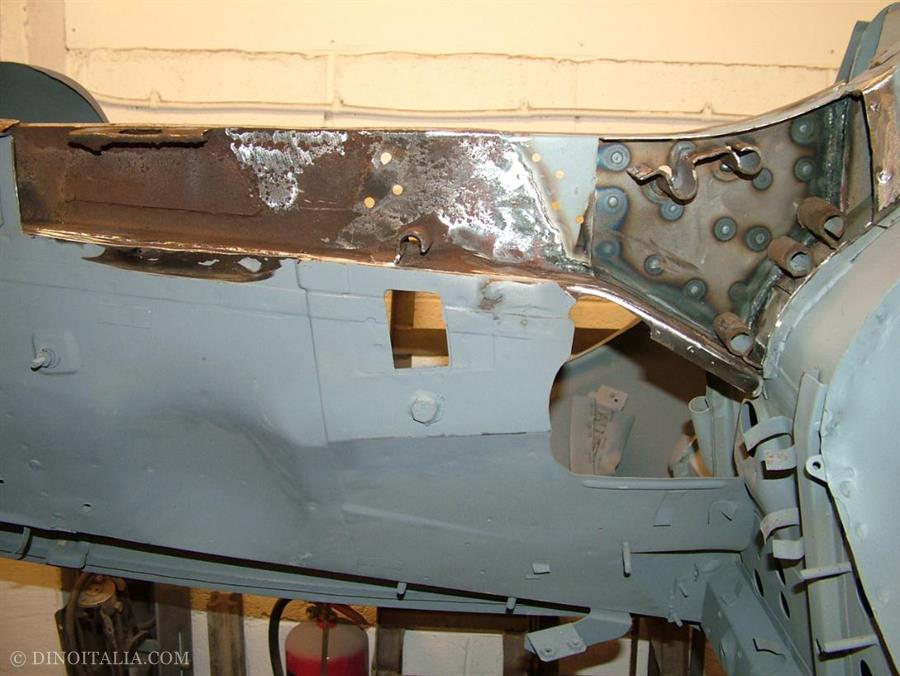
Front chassis rail cut open to expose inner structure. A new chassis rail sleeve panel has been made with the steering box stiffeners fitted. If you refer to our 2 litre Spider restoration there is an explanation of how the front chassis rails fit onto these sleeves.
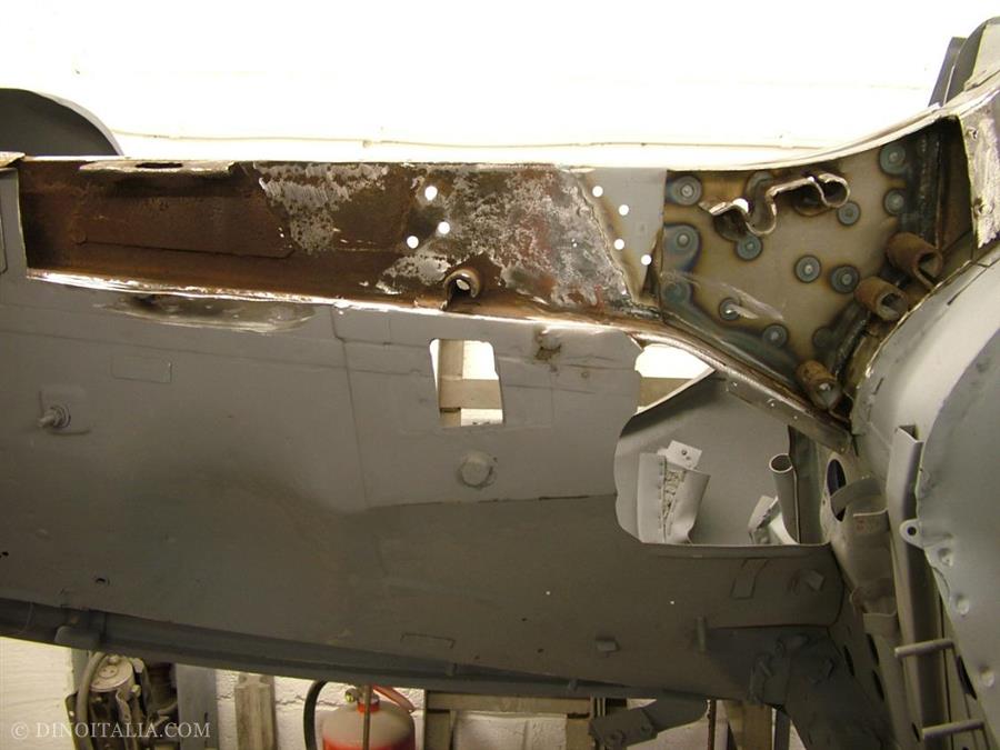
Another shot of the inside of the chassis rail.
This shows the chassis rail lower closing panel removed.to espose the corrosion inside.
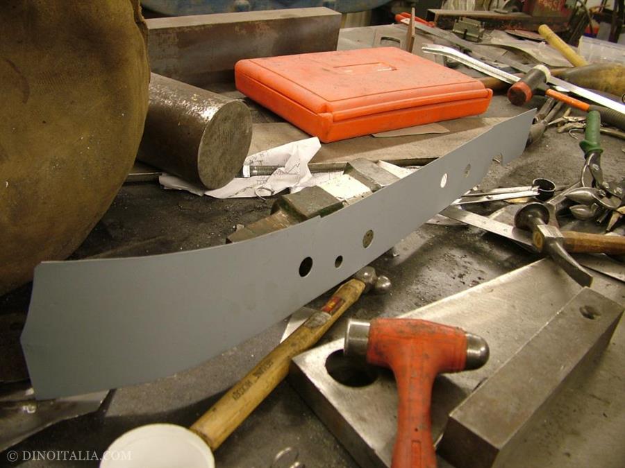
The new chassis rail closing panel.
Chassis rail sleeve fully repaired, ready to be enclosed inside the chassis rail.
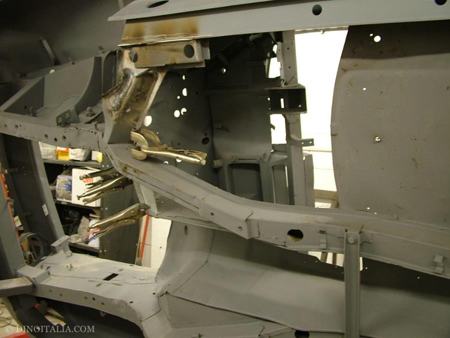
Front chassis rail finished with just the upper suspension mount area awaiting a little attention.
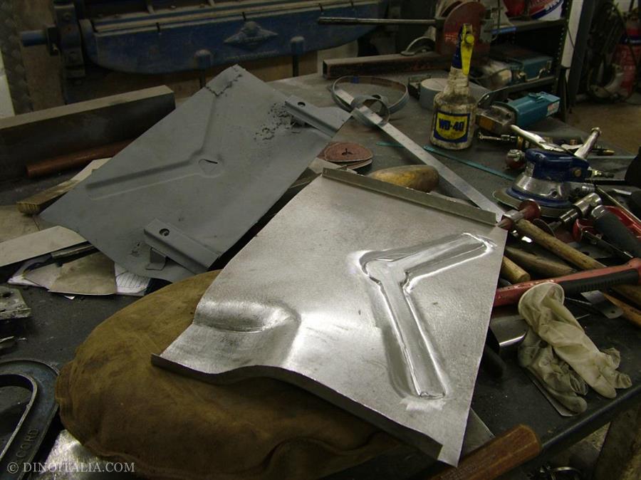
New engine/gearbox cross member strengthening plate with captive nuts.
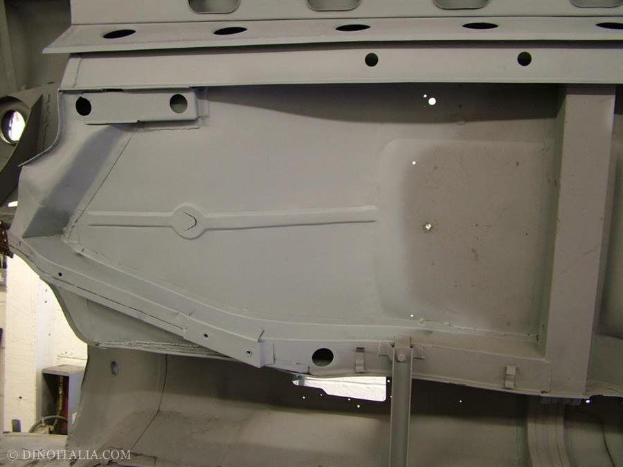
The finished front floor pan.
Front floor pan being checked for alignment during construction.
Outrigger straightened. These are often damaged by people jacking the car up on them.
Rear floor pan removed.
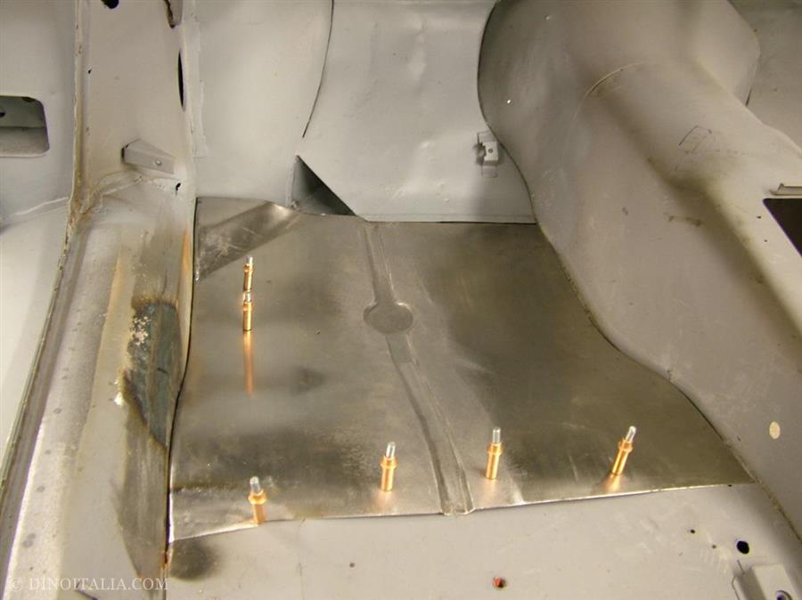
New rear floor pan.